SCOPE
STANDARDS
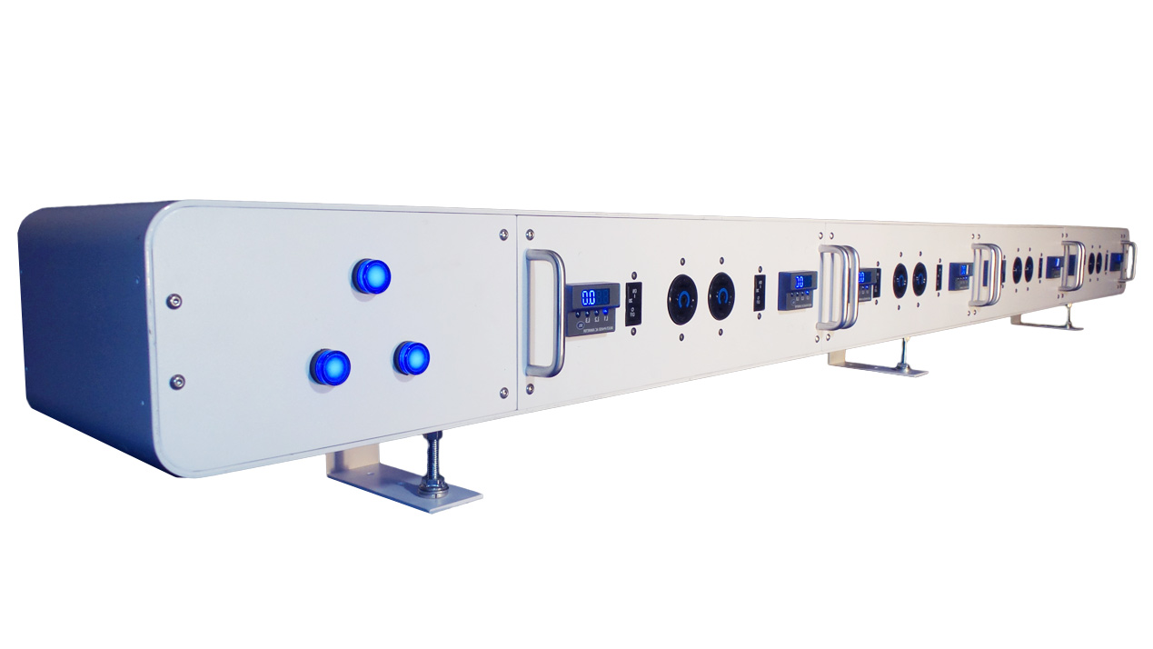
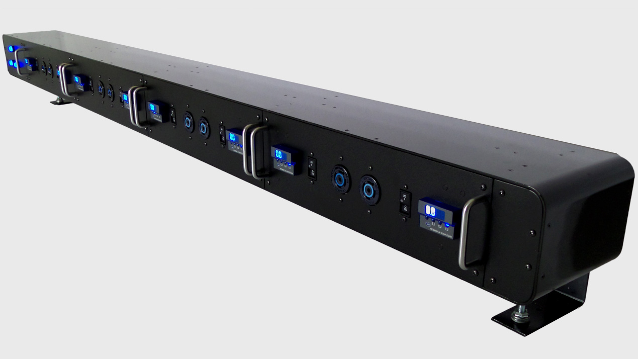
SYSTEM DESCRIPTION
Input/Output voltage shall be ((208/120), (240,120), (400/230)) volts AC, ((50/60)) Hz, three-phase, four-wire-plus-ground or single phase, three-wire-plus-ground.
Storage temperature range shall be -55 to +85°C (-67 to +185°F).
Operating temperature range shall be 0 to 40°C (+32 to 104°F).
Operation shall be reliable in an environment with 0% to 95% noncondensing relative humidity.
The audible noise level of the specified system shall be less than 45dBA.
DOCUMENTATION
Wiring diagrams and drawings of major components shall be furnished.
A list of recommended spare parts shall be supplied at the customer’s request.
An in service user’s list shall be furnished upon request.
WARRANTY
The manufacturer shall provide a one-year warranty against defects in material and workmanship for 12 months after initial start-up or 18 months after ship date, whichever occurs first. (Refer to the Warranty Statement for details.)
QUALITY ASSURANCE
The specified system shall be factory tested before shipment. Testing shall include, but shall not be limited to: Quality Control Checks, “Hi Pot” Test, two times rated voltage plus 1000 volts, per UL requirements (Metering Calibration Tests), and load test of individual receptacles within the unit.
COMPONENTS
Dual Input power conductors shall connect to the two sets of main lugs or terminal blocks. Power terminals shall be provided for connection of a 150% rated neutral (1/O power cable, and ground). A Main Input power terminal blocks shall be provided for connection of the input power conductors, 150% rated neutral, and ground.)
Distribution unit shall be protected by an external main 150 amp circuit breaker (Maximum). The breaker shall be UL listed and IEC rated for use at the system voltage.
The specified system shall contain electrical bus for each phase, neutral and a ground lug for distribution to the intended receptacles and/or loads. The bus shall be accessed from the front of the unit. The electrical bus shall be totally enclosed with a removable accent panel that provides access to that bus without exposing other portions of the unit. The electrical bus shall have a rating of minimum 190 amperes, with an overall short-circuit current rating of 10,000 RMS symmetrical amperes. The electrical bus shall provide a total of 24 single-pole connection points for internal and external receptacles. The electrical buses shall include separate isolated neutral and safety-ground bus bars for the neutral and safety-ground connections for at least 12 output circuits. The neutral bus bar shall be sized for at least 1.50 times of full load rating to accommodate high harmonic neutral currents associated with single-phase nonlinear loads. The main power bus can sub-feed another PDU utilizing the same input power up to the full rating of the feeder breaker.
Each load circuit shall be protected by an individual branch circuit breaker. Single-pole, two-pole, and three-pole bolt-on ends type branch breakers up through 30 amperes shall be utilized. Each branch circuit breaker shall provide over current protection and shall clearly indicate the “ON”, “OFF”, and “TRIPPED” positions. All branch circuit breakers shall have a minimum interrupting capacity of [(5,000) (3,000)] RMS symmetrical amperes at [(120/208) (120/240) (400/230)] VAC. Each branch circuit breaker shall be sized in accordance with the NEC and shall be UL listed. Branch circuit breakers shall have an associated directory label identifying the branch circuit number and the receptacle being served.
The output of each circuit is internally wired to a dedicated receptacle on the power module of the HPDU. The cable supplying each remote load shall consist of UL/CSA listed liquid-tight flexible metal conduit containing the required THHN copper insulated power, neutral, and parity-sized ground conductors. The flexible conduit shall be liquid-tight, insulated, and shielded to minimize electrical or mechanical disturbances to the conductors. The length of each cable and the type of receptacle/termination shall be as specified on the detailed cable schedule. Each output distribution cable shall be permanently labeled at each end of the cable with the assigned circuit number and receptacle type, equipment identification, and cable length. Each cable shall be thoroughly factory-checked and factory-tested. Tests shall include continuity, phase rotation and a Hi Pot test at twice rated circuit voltage plus 1000 volts. All output cables can be wound on spools mounted on casters to facilitate handling and installation. Each cable shall be a UL listed assembly.
ACCESSORIES (OPTIONAL COMPONENTS)
The current monitoring meters shall consist of a 3 digit high visibility LED Display to monitor current parameters. Front LED’s shall be provided for operator interface. The display shall be accessible without opening the door. All currents shall be monitored using true RMS measurements for accurate representation of non-sinusoidal waveforms typical of computers and other sensitive loads.
The enclosure shall be provided removable cover that allow the operator to access the main and branch breakers.
Bolt on main circuit breaker for each receptacle shall be provided.
Heavy-duty solid wood crating shall be provided to meet international requirements regarding package strength and special markings for overseas shipments.
Factory start-up, preventive maintenance, and full service for the specified system shall be available upon request. The manufacturer shall directly employ a service organization of factory- trained field service personnel dedicated to the start-up, maintenance, and repair of the manufacturer’s power equipment. The manufacturer shall maintain a dispatch center 24 hours per day, 365 days per year, to minimize service response time and to maximize availability of qualified service personnel.